The previous two parts of the write-up of this project focused first on making the spindles and their holders, followed by machining the handle and the head with a dovetail focus. This article tackles a number of smaller parts for adjusting the height of the head on the arm before jumping back into head completion.
We begin with the height screw, its nut, bearing and knob. The height screw nut is a simple rod of brass with a threaded cross-drilled hole. The rod needs to be 3/16" in diameter and 3/4" long. The cross hole is located 0.100" from the end and tapped #6-32, so a #36 drill was used.

The second part to be made is the height screw bearing. A 1" length of 3/8" brass round was cut from stock. One end was faced followed by reducing the diameter to 0.313" for about 3/4". The end was center drilled, drilled with a #28, 0.140", drill, and not reamed. Turns out I don't have the required 5/32" reamer, so a 5/32" drill was used to open the hole. (Another tool to add to the purchase list.)
The diameter was further reduced to 0.188" for a length of 0.400". A cutoff blade was used to reduce the diameter of the part to 0.240, from 0.462" to the end of the part (another 1/16"). The cutoff blade was then used to part off the bearing. A flat is needed on one end of the bearing and this was cut in the mill, held in the vise with the aid of an inserted #22 drill.


The next part to make is the height adjustment screw. A 2+" length of 3/8" drill rod was cut from stock. It was reduced to 0.188" and then one end was reduced to 0.140" for 15/16" and threaded 32 TPI, first by single pointing on the Sherline and after reaching about 0.03" depth the thread was finished with a #6-32 die. The opposite end was reduced to 0.156" leaving a 3/16" shoulder in the middle and then parted off at a total length of 1.763". The photo below shows the screw at this stage. The screw was held with a clamp on top of two pieces of wood. In this fashion a flat was filed on the end of the part.


The next part for this height adjustment mechanism is the handle for the screw. It needs to be knurled. I considered waiting to make this part or remaking it once this project is complete, but decided to give press knurling one last chance, the result surprised me. A 3/8" bar of hex was reduced to 0.313" for 1". The rod was coated with cutting fluid and the knurling tool moved on to the part from the well-chamfered end. The knurls seemed to track well, though always difficult to see what is going on with the gray cutting fluid coating everything. After removing the home-made knurling tool holder and wiping off excess fluid a nice knurl was exposed.
The free end was reduced to 0.24" for 0.156", center drilled and drilled up to 5/32". The opposite end of the knurl was also reduced to 0.24", leaving 0.219" of knurled steel between the two reduced sections. The screw handle was parted off 1/16" from the end of the knurl and the new end faced. The part was moved to the mill where it was centered by eye and a hole was drilled and tapped for a #4-32 set screw, as I don't have either the smaller #3-48 set screw recommended by the author, or a #3-48 tap. After cleaning out the burrs inside the handle the screw was installed.


The next two parts are identical and are levers. One is for the clamp holding the arm tight to the head. The article makes these from steel, but I went with brass to add a little color. A scrap of brass 1/4" X 3/8" was located. It was painted with Dykem™ blue. Locations for centers of the rounded ends were marked and lightly punched. Circles were scribed from these centers. The back of the part was milled so the total thickness is now 7/32". The back was then marked with two lines both located 1/4" from the small circle centers. This small end of the lever remains at the 7/32" thickness.

Particularly like the reflection of the dental mirror in the polished granite block, though don't know what the mirror is in turn reflecting. This is not a surface plate, but a cutout from a granite installation in the kitchen. The polished granite surface has proven effective, though I have no way to verify its flatness beyond visually using a backlit straightedge.
A 1/4" rounded end end mill, a smaller one would have been nice if I had one, cut the part down to 3/32" thick producing a filet at the scribed line. The remainder of the lever was reduced to 3/32" with a 5/16" end mill. This was repeated on the second lever.


The two parts were cut from the blank with a hacksaw. The angled sides were cut via the simple expedient of aligning the scribed line with the top of the milling vise. All four sides were cut producing the two roughly cut levers shown below.

The two levers were roughly sanded on the disk sander with 120 grit paper. With very light touches the desired circular profile was shaped on the ends. The photo below shows the levers after this sanding.

The levers were then sanded with 220 grit sandpaper by hand. All of the corners on the lever tops were rounded. The levers at this stage are seen in the first photo below. The levers were then sanded with 320, 400, & 600 grit sandpaper for the final finish. I prefer this softer look to the bright polish achieved with finer grit sandpaper.


The two levers will be soldered to two screws, the height lock screw and the spindle housing lock screw. The height lock screw was made first from a short length of 3/8" hex steel. One inch was turned down 0.375" and one end was then center drilled, held with a tailstock center and 0.875" was turned down to 0.250". After threading, 28 TPI, on the Sherline the opposite end was turned down to fit the lever. The first photo shows the completed screw and the second shows it posed in a lever.


The same process was followed for the longer spindle housing lock screw and it is shown below in front of the height lock screw.

The parts were washed with soapy water, rinsed with H2O and rinsed again with acetone. While holding the screws in the vise, the levers were set in place. The joint was fluxed and small bits of silver solder were applied. The joint was heated with a propane torch until the flux boiled off and the solder melted into the joint. The first photo shows the parts still hot and the second after washing and sanding with 600 grit sandpaper.


The last part to make in order for the height adjustment mechanism to be functional is the washer. A length of brass scrap, 3/8" diameter with a 1/4" hole was held in the milling vise on parallels. The top was milled 0.031" ⊥, while leaving a 0.031" unmilled edge. The part was held in the lathe and parted off at 3/32" from the milled edge. The part is shown below and after some sanding on the screw, the fitted washer is shown in place screwed into the handle.


The lever is not in a good place when locked as seen above, it should be closer to 2-3 o'clock. This was fixed per the article by filing the washer. The lever more correctly aligned to stay out of the way is seen below.

It was time to assemble all of the parts made so far for height adjustment. The knurled knob was removed from the screw and the bearing installed prior to reinstalling the knurled knob. The height screw nut was put into the drilled hole in the handle with the tapped hole sticking out. The head did not slide onto the handle as the nut was a tad too long. This was quickly rectified in the lathe and the nut was put back into the hole. The head slid onto the handle and the height adjustment screw was threaded through the hole in the head and into the nut buried in the slot in the dovetail. This modified the angle of the height lock screw lever, so a bit of back and forth with filing and other adjustments finally gave a nice setup. The first photo below shows the height adjustment screw assembled and the second the complete setup of the head and handle.


We now return to the head and its internal components, starting with the cotters, not something I have ever made. Cotters are for tightly holding round parts sitting in a bore. These cotters begin life as one piece. A 1 3/8" long piece of 3/8" brass was cut from stock. The piece was faced on both ends. One end was marked out with the height gauge. The part was held in a 3-jaw chuck, which was screwed onto my version of a four-sided collet block. The block was set on two 1-2-3 blocks. The height gauge located the top and was lowered 3/16". A mark was scribed across the end. The block was turned 90° and a second mark was scribed after lowering the height gauge an additional 1/32". The intersections was prick punched and then punched for drilling.
The part was moved to a 4-jaw chuck on the lathe spindle and the punch mark was set on spindle center. After center drilling a through hole was drilled with a #3 drill. This hole was opened for half the length of the part with an A drill and then reamed 1/4". The smaller diameter end was tapped in the vise 1/4-28. This will be the last addition to this project for two weeks, a sculpting class next week at MASW, followed by four days with the youngest two grandkids. A few days of recovery will be necessary.

Returning to this project has taken longer than planned. The sculpting class left me with a partially finished sculpture that I have been trying to complete. Of course that implies using the woodshop. The benchtop has not been visible in a couple of years, so cleaning preceded the sculpting. One week and many bags of waste were removed along with vacuuming and rearrangement of stored items resulted in a clean work surface, the first time in many years that this surface has been seen in its entirety. The workbench is now usable except for the left end that is permanently blocked by the router table.

The wood sculpting was completed and can be seen in a post. In the interim two major issues arose that again delayed a return to this project. One of the issues was discovered when installers came to replace carpeting with hardwood flooring. Two surprises were uncovered when the carpet was removed. The first was rotting wood under a living room window. The subfloor was wet as was the joist under the wall. The second thrilling discovery was that when the house was built 36 years ago the floor joists in the four rooms, where the wood floors were to be laid, were not installed level. In fact they are so far from level that the wood floors cannot be installed without repairs! In the meantime we are living in a house that is mostly unusable. This kind of excitement I can do without! The rotten joist will be repaired early in November and after that the floor work will commence.
The second issue was an unexpected illness in the family, unfortunately followed by the family member passing. The two week hospital stay and the flooring work happened simultaneously. Quite the end to September. It is now October and past time to return to the shop.
Began with a trivial bit, a washer to fit the 0.375" hole in the head. This part is just a temporary way to provide relief below the cotters. A #6 washer was held on a quickly fashioned screw with nuts on either side. The screw threaded on the end of a length of steel hex was held in a chuck and the washer reduced to fit in the hole.
The next part to be made, prior to finishing the cotters, is the back plate. This requires a length of 1/8" X 1" steel, which I don't have. So off to the SpeedyMetals website to order this and some other brass and steel which I am low on.
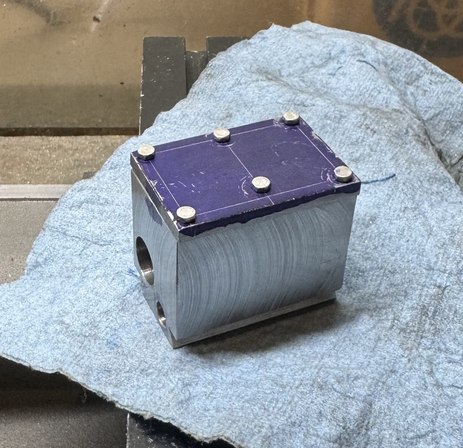
It is now past mid-October and the temps are dropping. The backing plate was cut from the newly arrived 1018 steel and milled to size, 0.938" X 1.375". The plate was painted with Dykem™ purple. Using the height gauge the corner holes were marked with lines 3/32" in from all four edges. The length of the plate was measured at 1.371" and a line was scratched at half of this distance. A final line on one side crossing the center line was scribed at 0.203" from the edge. Six intersections of the lines were punched first with a prick punch and then with the sliding punch. The photo below shows the resulting plate marked for drilling.

I took a slightly different path to drilling the holes in the plate and the head than the article described, as opposed to drilling the plate and marking the head for holes I clamped the plate to the head prior to drilling both. The plate, by design is wider than the head, though the pictures tell a different story, maybe I missed a later errata? Two opposite edges of the plate were marked with a center line and the same was done with the head. The center lines were aligned and the plate clamped to the head with two small homemade machinist's clamps.
The clamped assembly was held in the milling vise and drilled with the #50 tapping drill to 0.285" deep. The plate was removed and the head tapped #2-56 for all six holes. The holes in the plate were then opened with a #44 drill. These holes were lightly chamfered on the inside to remove drilling burrs. Hex head screws were put in place as seen in the photo below. Between 3/32" and 1/8" needs to be removed from the screws for them to clamp the plate in place.

Looking closely at the photo above reveals how close two of the holes were to the side of the head, just hinting at the threads inside.
Six screws were cut off with a hacksaw using a screw cutoff jig made in 2009, one of the first write-ups on this website. Each shortened screw was screwed into two nuts and the ends filed. Removing the nuts straightened the threads so they were an easy fit in the body. The six screws in place are shown below.
Talk about "Hall of Shame" blunders—the holes were drilled on the wrong side of the head!!!!!!! No wonder it didn't fit!!!!! After feeling sorry for myself a repair was initiated.
Six full length screws were pulled from the stash. These were installed tightly in the wrong holes with Thread Locker™ and left to harden for 24 hours. These repair screws are seen in the first photo below. The second photo shows the block after hacksawing off the screw heads. The third the block after filing the screws flush.


Okay, now I am back where I was two days ago. The difference this time is that the holes now need to be transferred from the plate. So a transfer punch was needed and I don't have one small enough for the #44 holes in the plate. A 2" length of 1/8" drill rod was cut from stock and both ends faced in the lathe. One end was turned down to 0.086", a sliding fit in a hole in the plate. The end of this reduced section was cut to a point after rotating the headstock 20°. The punch was heated to cherry red and quenched in motor oil, hardening the steel point.


The plate was clamped to the head, on the correct side, with two small machinist's clamps. While holding the clamped assembly in the milling vise, the six holes were transferred from plate to head. The holes were enlarged with a spring punch.


With the holes transferred the head without the plate was held in the milling vise. All six holes were center drilled, drilled with a #50 drill 0.160" deep, and tapped 2-56. The block after tapping all holes is seen below along with a photo of the plate screwed to the block. Back in business!!


Some of the holes needed to be drilled through the installed screws, worrying me that I might break a drill. While drilling I could feel the drill encounter the screws as they are harder than the surrounding steel. A lot of cutting fluid and slow careful drilling avoided any issues the screws might have caused.
The two holes for the spindles were tackled next. Both are located 3/8" from an end of the head and 5/16" from the edge opposite the dovetail. The holes intersect the cotters, which need to be drilled simultaneously, so the cotter was inserted in its hole on top of a washer. The washer is only temporary and provides the eventual cotters some slack in positioning. The cotter was clamped in place with a C-clamp.
The head with clamp was held in the milling vise and the edges were located. The spindle was moved to the appropriate location and drilling commenced with a center drill, followed by a 9/32" drill. The hole was opened in steps to 3/8". The drill chuck was swapped for the boring head, with it set at its minimum diameter, 3/8".
Struggled with boring on the Sherline mill, just too much chatter and minimal cutting! Took some time for a rethink on how to procede. In the meantime a walk this morning was clear. The photo below shows two planets in the early morning sky, Jupiter in the middle and Mars at the top. The bottom stars are part of Libra, I believe. The moon was almost full, but I was not able to get a decent photo with the phone's camera. It was overexposed and I don't know enough about the phone to fix that problem.

After the walk and breakfast the head with its clamp in place was moved to the four jaw chuck on the South Bend lathe. A dial gauge was used to center the hole. The hole was then bored to just under 0.500" and reamed with a 1/2" reamer. One hole complete.

Reaming a 1/2" hole is not possible in the Sherline and probably not a good idea anyway. The reamer is too long. It could be cut off, but a reamer that large is too taxing for the small machine.
The second hole was quickly completed as the first hole provided the needed guidance. The first photo below shows the two holes and the clamping setup in the four jaw chuck. Note the scrap of aluminum holding the cotter in place. The second photo shows the spindles posed in their new holes.


The cotter was sawn in half with the hacksaw. Both of the newly cut ends were faced such that only about half of the drilled depression remained. The threaded cotter was dropped into its hole with the depression facing the bottom spindle hole. Both spindles were put in place followed by the upper, unthreaded cotter. The cotter screw was installed through the top cotter and into the bottom. A few turns and both spindles were tightly clamped.

The last operation performed for this part of the project is drilling two 3/16" holes in both the head and the plate. After removing the spindles and cotters the plate was installed on the head. A corner was located and the spindle located over the first hole. The hole was center drilled and drilled in two steps, then reamed 3/16". The depth was closely held to 0.375" in the head or 1/2" with the plate in place. The spindle was moved 0.250" and the second hole was similarly made. The photo below shows the two completed holes and concludes this third part of the cut knurling tool build.
